
Components needed for this board:
2x 560ohm resistors2x 1kohm resistors
2x PNP transistors
2x 5mm L.E.D
Calculations to figure out what resistors were needed:
We needed to figure out the resistance for R1, R2, R3 and R4 to get the correct resistors
The data needed to calculate this was found on a datasheet I found online:
http://www.datasheetcatalog.com/datasheets_pdf/B/C/5/4/BC547.shtml
R1 = (V-L.E.D/I) 12-1.8/0.20 = 510ohm/560ohm resistor
R3 = same as R1's calculation.
R2 = (signal-V.D/Ibe) 5-.7/0.005 = 860ohm/1kohm resistor
R4 = same as R2's calculation
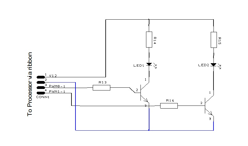
How it works:
This circuit has a 12v in, which runs through each 560ohm resistor which are both set up in a parallel circuit. From the resistors the current flows through the L.E.D's into the collectors. A 5v signal current is then sent through the 1kohm resistors which are also in a parallel circuit, this 5v signal current then flows to the base allowing the transistors to saturate meaning that the current can flow from the collector to the emitter, so therefore the L.E.D's are supplied with an earth as well as a Vin current which allows the L.E.D's to emit light.
This circuit has a 12v in, which runs through each 560ohm resistor which are both set up in a parallel circuit. From the resistors the current flows through the L.E.D's into the collectors. A 5v signal current is then sent through the 1kohm resistors which are also in a parallel circuit, this 5v signal current then flows to the base allowing the transistors to saturate meaning that the current can flow from the collector to the emitter, so therefore the L.E.D's are supplied with an earth as well as a Vin current which allows the L.E.D's to emit light.
Testing to see if circuit is correct:
First I started by testing 12v in voltage to see if i was getting enough current, my Vs reading was 12.2v so i adjusted this to 12v at power supply because that was the specified voltage. After Vs was tested, i tested the volt drop across both the 560ohm resistors and Vd reading was 9.7v, then from there i tested the volt drop across the L.E.D's and they were using the left over voltage which was 2.3v, which is correct because according to the data sheet for these particular L.E.D's the max power dissipation without damage was 2.5v. I then tested both the signal in's for the base port, the volt drop between them was slightly to much at 4.8 volt so I decided to change the resistor to a lower value resistor to allow the the base to saturate. After this was changed I tested the volt drop again and the result was alot better being 4.4v. After this change it allowed the base to saturate resulting in the L.E.D's lighting up.
Problems found:
There was one problem found, the resistors I used for the base port were of to higher value so they weren't allowing the base to saturate, I then changed those for a lower value resistor resulting in the base to then start saturating.
Reflection:
If I was to re built this circuit, I would make my soldering alot neater than it is, I would also try to make it more compact to save board space. But other than that I am quite happy with the result I have gotten out of this circuit.
Sorry about the bad quality photo, but it is of the circuit board working

Hi Josh you are missing the Beta calculations, also a all the volt drops (should be 11) and their explanations of what they are telling you
ReplyDeleteHowever your on the right track